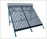
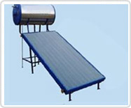
By gravity flow, water from the cold-water tank enters the solar tank at point through cold water inlet and fills it up. The cold water from the solar tank in turn flows in the bottom header pipe of the absorber, and into the copper tubes, until all the absorber tubes and the header at the top of the absorber are full.
When the sun rises to a certain level, its energy, which falls on the absorber fins and tubes, begins heating the water contained therein. The heated water being lighter than the cold water rises and via the top header pipe of the absorber, flows into the top of the solar tank through pipe. The quantity of hot water entered in to the solar tank, same quantity of cold water from the solar tank flows into the absorber tubes, gets heated and rises to the top, and so on. This process is called ‘Thermo-syphon Process’ and this Thermo-syphon Process continues until the temperature of the water in the solar tank and the absorber equalizes. Now the solar tank is full of hot water. Average temperature is 60 degree centigrade at the end of bright sunshine day.
Further when the hot water is drawn from the solar tank outlet to the utilities point, cold water enters into the solar tank and takes its place, thus lowering the overall temperature of the hot temperature between the water in the solar tank and the absorber tubes, the thermosyphon process starts once again, as explained earlier.
A back up electrical heater (to be used during cloudy days) and the sacrificial anode rod in the solar tank to prevent galvanic corrosion (but not scale formation), if the hardness of the water quality is less than 140 ppm, thereby ensuring effective working for longer time.


Solar Water Heaters are available in Three models and capacity ranging from 100 LPD to 1,00,000LPD
TECHNICAL SPECIFICATIONS OF REGULAR SOLAR WATER HEATING SYSTEMS
| COLLECTOR | ||
| 1 | Absorber material | Electro Grade-Copper-Copper |
| 2 | Absorber Coating | Selectively coated continuous electroplating of black Chrome over nickel substrate on copper sheet of 0.2mm thickness with Heat treatment to withstand temperature up to 300 deg C. Optical property Absorptivity = 0.96 +/- 0.02, Emissivity = 0.12 +/- 0.02 |
| 3 | Riser | Copper tube of dia. 12.5mm +/-0.5mm,Thickness 0.56mm |
| 4 | Header | Copper tube of dia 25mm +/- 0.5mm,Thickness 0.71mm |
| 5 | Bonding b/w Riser & Header | Brazing |
| 6 | Bonding between Fin & Tube | Ultrasonic/TIG |
| 7 | Back Insulation | Resin bonded Rock wool of 48 Kg/m3, Thickness 50mm |
| 8 | Side Insulation | Polyurethane, Thickness 25mm |
| 9 | Collector Box | 100mm X 25mm Aluminum channel, Thickness 1.63mm with Polyester Power Coated to avoid fading and scratch. |
| 10 | Collector Bottom Sheet | Aluminum, Thickness 0.71mm |
| 11 | Collector Stand | Corrosion resistant MS Acrylic Coated – 35 x 35 x3mm |
| 12 | Glazing | Toughened glass, Thickness 4mm with low Iron Transmitivity :>85% @ near normal incidence |
| 13 | Retainer Angle for Glass | Aluminum Angle, size 25mm X 25mm X 1.6mm |
| 14 | Beading for Glass | EPDM Rubber |
| 15 | Absorber Area | 2 sq. meter +/- 0.1 sq. meter / Collector |
| 16 | Wt. of the Collector (dry) | 60 Kg |
| 17 | Collector Tilt | 24.5 deg to HORIZON (non-variable) for places located between12 deg North and 15 deg South |
| 18 | Heat Transfer Medium | Water |
| 19 | Collector Area | 2.132 .sq meter |
| 20 | Number of Fins | 9 |
| 21 | Maximum working pressure | 6 kgf / cm |
| 22 | Dimensions | Length – 2050 mm, Breadth – 1040 mm, Height – 100 mm |
| 23 | No. of Collectors | Nos |
| HOT WATER STORAGE TANK | ||
| 1 | Material | Stainless Steel, AISI 304 |
| 2 | Insulation | PUF – 40 mm thickness (CFC Free) |
| 3 | Outer Cladding | Stainless Steel, 430 Grade |
| 4 | Inter Connecting Pipe | High Pressure Steam Hose Pipe assembly with Check Nut |
| 5 | Electrical Back-up Heater(With thermostat) | 03 KW to 12 KW up to 3000 LPD capacity. For higher capacity, heaters will be provided accordingly. |
| 6 | Connecting Pipe | Stainless Steel |
| 7 | Standing Losses | 2° – 3°C |
| 8 | Maximum working pressure | Atmospheric |
| 9 | Sacrificial Anode | To avoid galvanic corrosion. |
| 10 | Tank Stand | Mild Steel (MS) with acrylic coating ISMC ( 100 x 50 x 6mm) |
| Continuous water supply should be available from an overhead tank, 7 ft above roof level for Domestic systems, and 10 ft for Non-Domestic systems | ||

